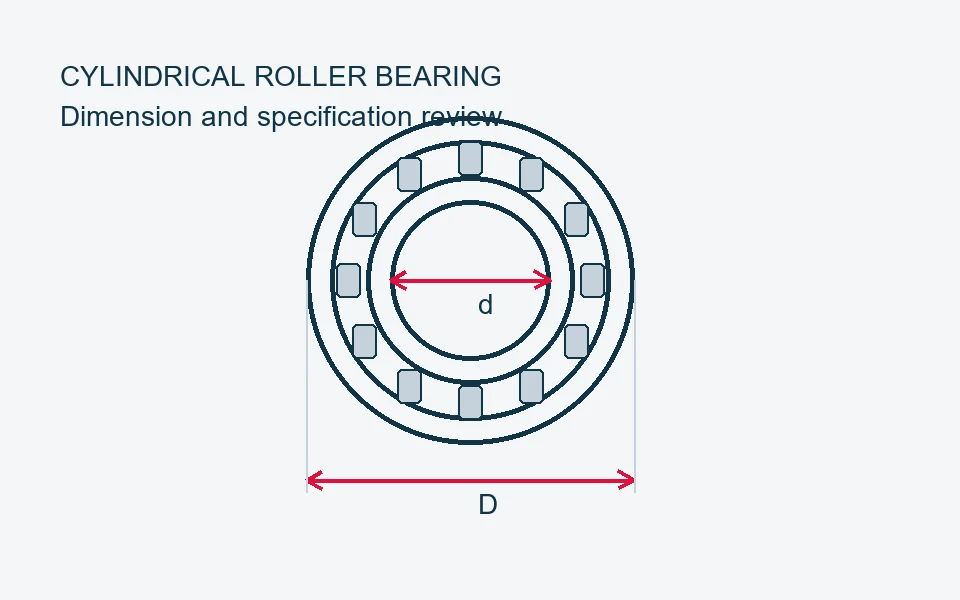
Inspection scope and acceptance criteria are confirmed for the bearing type and order requirements. The diagrams below explain inspection topics; they are schematics, not photographs, measured results or step-by-step test instructions.
01
Bore & outside diameter
Review the boundary dimensions.
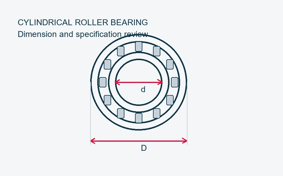
Check bore d, outside diameter D and width B against the drawing and specified tolerances. Use an appropriate measurement method and record the units, measuring conditions and acceptance limits.
02
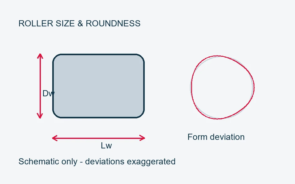
Roller size & roundness
Control the geometry of the cylindrical rollers.
Define roller diameter, length and relevant form requirements in the inspection plan. Diameter measurement and roundness evaluation are separate checks; the method and acceptance limits must match the component specification.
03
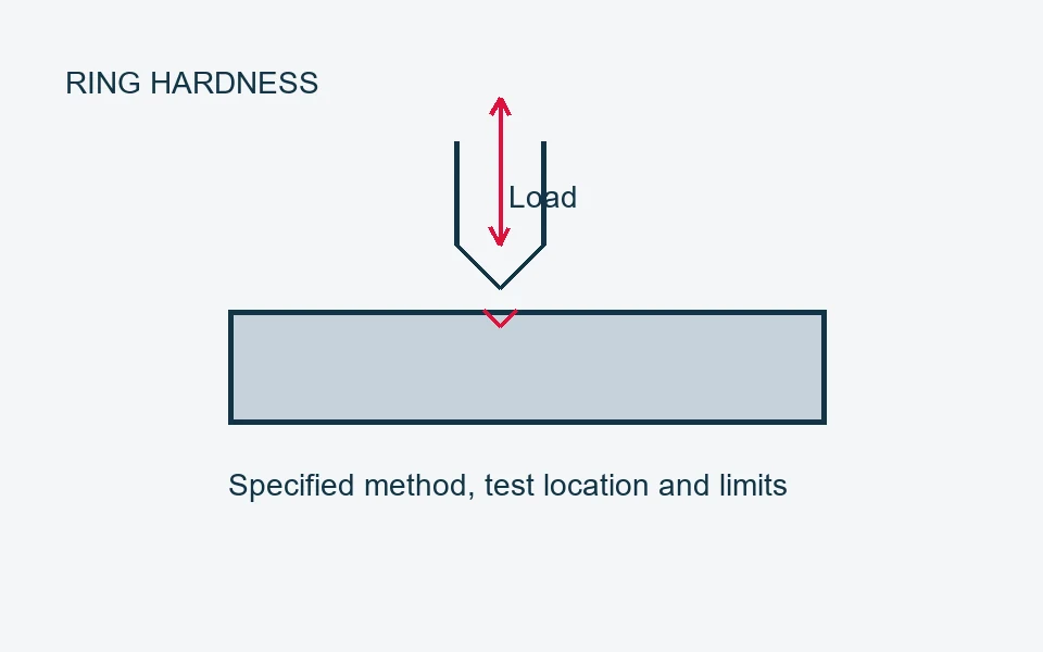
Ring hardness
Confirm the specified hardness requirements.
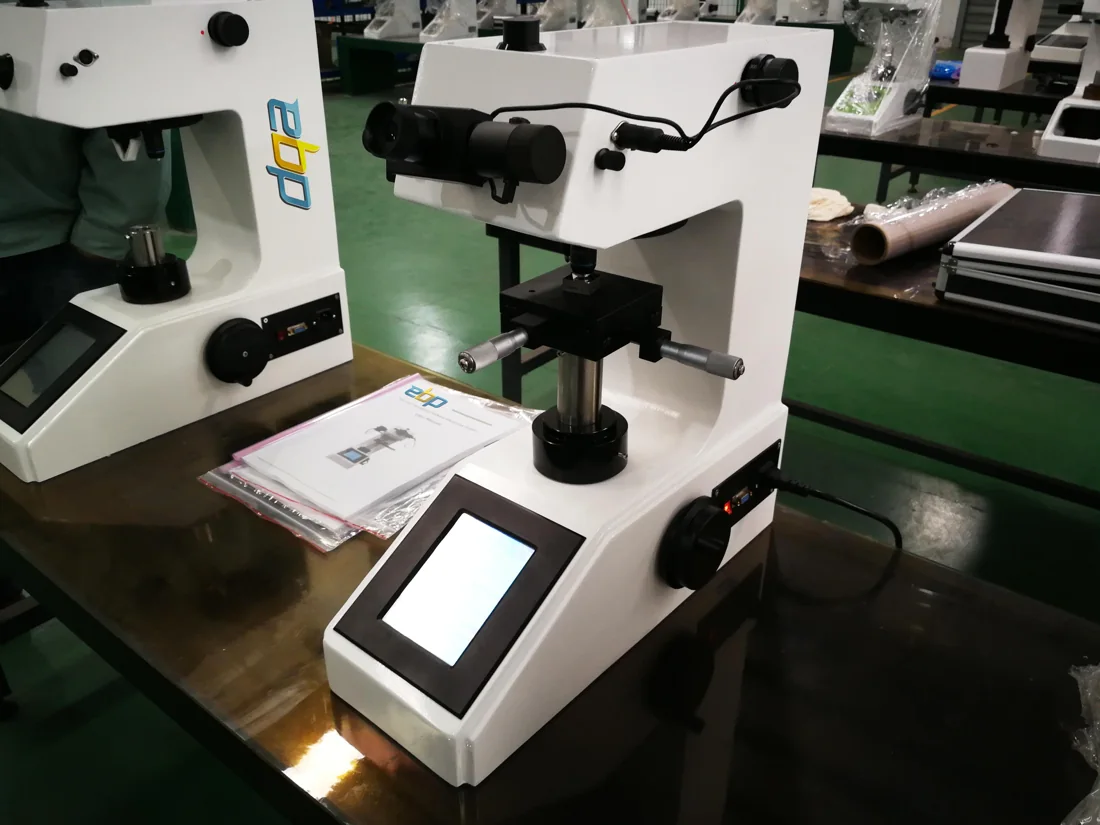
Agree the hardness method, test location, sample preparation and acceptance range for the ring material and heat treatment. Rockwell and micro-Vickers results should be reported with the correct scale and test conditions.
04
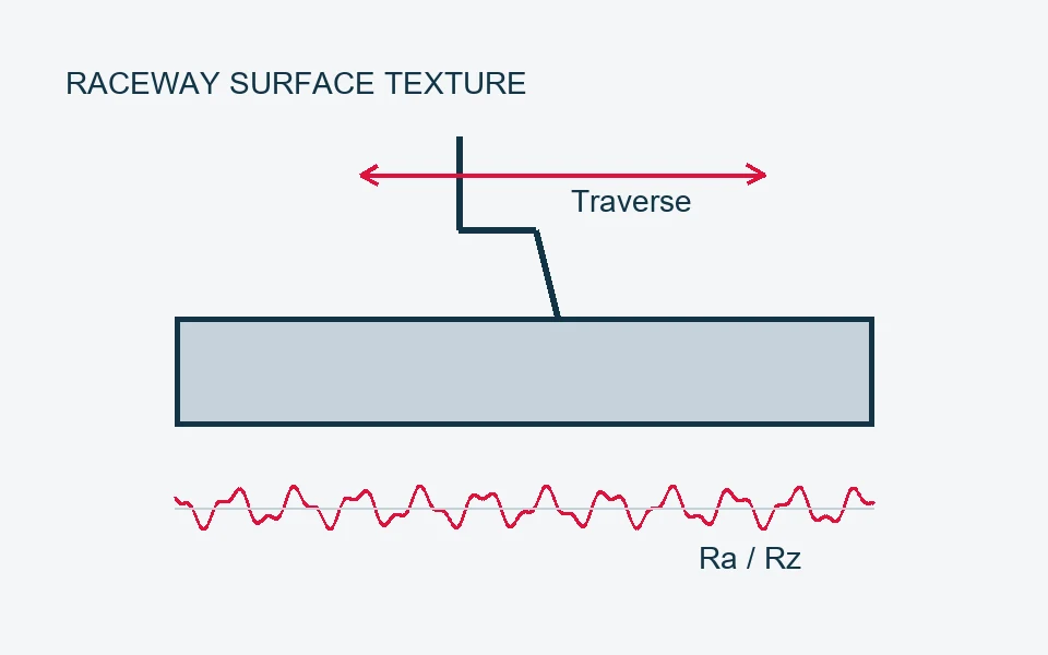
Raceway surface texture
Review the rolling-contact surfaces.
Assess the raceway surface condition and specified roughness parameters, such as Ra or Rz. Measurement direction, filtering and evaluation length should be defined for the agreed surface texture requirement.
05
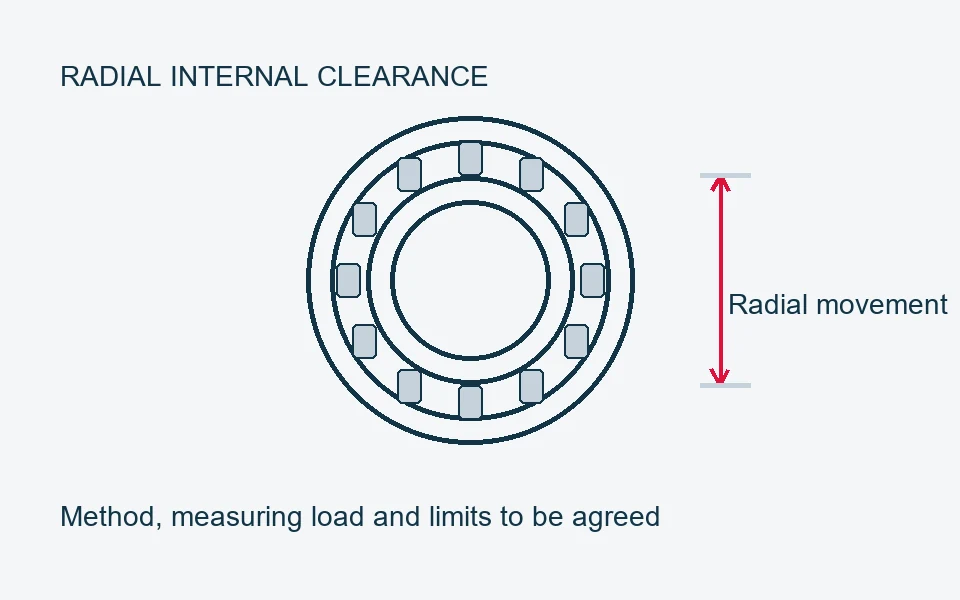
Radial internal clearance
Check clearance for the selected arrangement.
Confirm the specified clearance group and applicable limits for the complete cylindrical roller bearing. Define measuring load and method, and distinguish unmounted internal clearance from clearance after mounting or during operation.
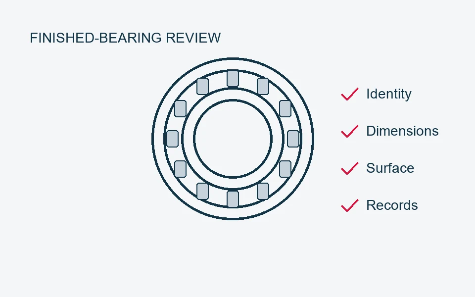
06
Finished-bearing inspection
Match the finished bearing to the order.
Review the complete NU, NJ or NUP designation, cage, dimensions, specified clearance, surface condition and agreed inspection records. Confirm preservation, identification, quantities and packing before dispatch.